Very accurate digital clock


ex-station-clock

A recent discussion of clock/calendar chips on one of the local email lists coincided with me reminding myself that I own a very decent clock with respect to drift.

I’m taking my amateur radio station apart (hadn’t turned the radio on in two years despite the sunspots peaking again: a very clear indication of my remaining interest in this hobby). I just moved the station clock indoors. It had been in an unheated room and I’m sure the time hasn’t been set in at least three years. The temperature went up and down constantly out there, to the upper 30s in the winter and upper 80s in the summer (the volume of air in the surrounding barn levels things out). Anyway, I just set the clock to EST and had to fix the minutes: off by two. So figure it was off by 179 seconds after 36 months. That’s 2ppm, what would be considered extremely good in a clock calendar chip such as the DS3231. All kidding aside, Radio Shack makes some decent stuff!

Nordson EFD Solder Paste

SAMSUNG CAMERA PICTURES

A very nice treat from the PCB Carolina show last week was this set of samples from Nordson EFD. With Freescale FXOS8700CQ magnetometer/accellerometer chips and a Sparkfun Heaterizer XL-3000 on the way I need to get with it, get a PC board design off to OSH Park and prepare to use small SMD components. The Heaterizer is a stop gap while my hot air tool budget catches up with desire, and I’m hoping to get some lessons from a friend with professional equipment. But with this top quality solder paste I think I’m approaching critical mass. Thanks to John Conti of Nordson EFD for the technical info and support for my modest goals.

Even if you’re not interested in the Sparkfun $10 hot air tool you might find the instruction manual fun to read. But seriously, folks, this surface mount tutorial at the Sparkfun site makes it clear that individuals inexpensive tools can join in the fun.

UPDATE FROM 2021: The SparkFun Heaterizer was incapable of surface mount soldering. I ended up using a cheapo Chinese oven until I could modify a convection oven with interior hi temp reflective material and thermocouple/microprocessor control for proper heating/cooling profiles to do surface mount soldering. The oven is inside a decent fume hood with exhaust air out a flue for safety and to avoid any odor problems. The proper hot air tool came along too, but I still find it best to apply paste with a stainless steel stencil from OSH Stencils and use a reflow oven for professional level results, with the hot air tool for rework or the occasional expedient operation. Finally, the FXOS8700CQ is EOL and last possible purchases will be at the end of 2021, so time to find a replacement. A client and I are investigating the ST LSM303AG as an alternative. It isn’t lacks the capability to interrupt on magnetic vector magnitude events but the price is right!

One Sneeze Equals Hours of Picking Up

402sAtCarolinaPCB2013

This is a little plastic jar containing size “402” surface mount resistors. These resistors look like they belong in a pepper shaker. They were at a booth at PCB Carolina last week and there was a contest to guess how many resistors were in the jar. I guessed 10k, and that was good for a top ten finish, but the correct number was 10,863.

Hand soldering TSSOP packages with MSP430G2955 example

SAMSUNG CAMERA PICTURES

While researching an alternative to the Atmel 328p for the Pathfinder (compass data logger) project I decided I just had to try out the latest, greatest chip in the Texas Instruments “value line” G series, which is the MSP430G2955. This chip features 56k of flash, 4k of RAM, and more I/O than you can shake a stick at. This chip was only released a few months ago and none of the sources I can access had any stock yet. I’d been using the TI developer web site a lot the past couple years and decided to order a sample part for the first time. TI sent one immediately by FedEx. Hopefully this article will serve as a small, initial thank you. I’ve loved the folks at TI for 35 years since I was part of a company that OEM’d their computer systems. I still have fond memories of visiting the R&D sites in Dallas and Austin.

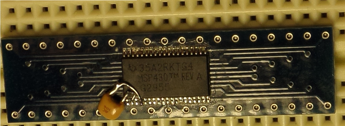
The problem, however, is that the least impractical package this device comes in is a 38 pin TSSOP package with .025″ lead spacing. Notice in the picture above there are four leads in the .1″ spacing between protoboard holes. Notice the bypass cap leads look like the Alaskan pipeline. (I used wire wrap wire to connect to the power and ground pins.) The most pointy soldering iron tip I own looks like the end of an unsharpened pencil in relation to this pin spacing. What to do?

I found a Youtube video (if I can find the URL easily I’ll paste it back into this blurb). It held the big secret: you solder a chip like this and then unsolder the spaces between the pins. Physics won’t allow the solder directly under the pins to be slurped out by braid type solder wick. Wow.

Here’s how to solder a chip like this. I assume you’re very experienced with soldering except for these itty bitty components and that you’re using a temperature controlled, low power iron with a tip so sharp that it’s painful to put your finger on it (when cold). A regular, small chisel tip iron might get the job done with the right (very small) amount of solder on the tip.

  • Meticulously clean the board with alcohol
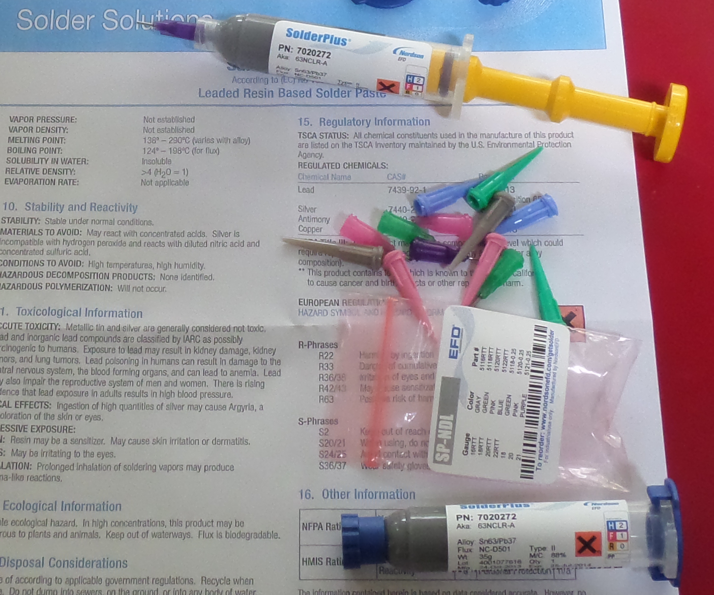
  • Apply liquid flux to the pads
  • Put the chip in place and slop more flux across two diagonal corners
  • Hold the chip EXACTLY right on the pads and touch the two corner pins with an iron holding the merest dab of solder
  • Put flux across both rows of pins
  • Put a length of very small gauge (e.g. 26 gauge) solder lengthwise across one row of pins, stopping short of the corner you tacked on.
  • Run the soldering iron across the pins, melting the solder and going at a speed such that you can see the solder wicking under the pins. IGNORE the fact that you’re soldering multiple pins together into unrecognizable blobs.
  • Put flux on some very small solder wick and lay it across a row of pins at a time
  • Put the iron across the flux and let it slurp excess solder off the pins a group at a time
  • Inspect the soldering with a decent magnifier and convince yourself there’s a nice solder joint under each pad
  • Ohm out the connections to confirm everything is right and there are no shorts or opens

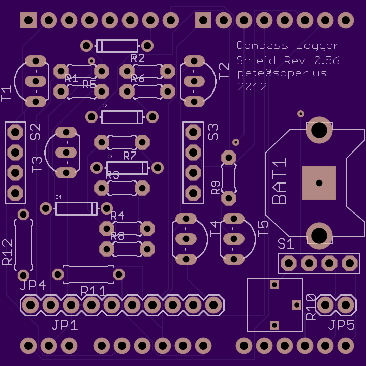
That’s it. I couldn’t believe that I could do this right the first time and when my health recovery allows it I’m going to have a blast with this chip. Some back of the envelope calculations suggest I can get the total quiescent current of the logger under a milliampere, so one large (nonmagnetic) Lithium coin cell may get the job done and run the logger for an entire summer of butterfly tracking, with the big flash memory standing in for the SD card used by the current logger.

By the way, the excellent quality DIP adapter came from a firm with a presence in nearby Morrisville, NC called EZ Prototypes. They had to ship my part from Boston but it got here in two days at a very reasonable price. Update September, 2019: This link is no good any more: the domain is no longer registered. Too bad. But anybody unable to find a 38 position adapter and  interested could ping me at pete at apexprotofactory dot com about making one, as this is a simple exercise for me now.

Logic Analyzers Rule

A few months ago I was using an Open Bench Logic Sniffer v1.04 from Dangerous Prototypes to decipher a problem with an SD card controller. It sure was nice to have a $50 device that works at least as well as the $5k devices I used in the 80s, and the performance is perhaps a hundred times greater than the tools I used with Intel and Motorola processors in the datacomm devices we created at Network Products.

Do it yourself Printed Circuit Boards

Top56

Last year I taught myself how to use the Eagle computer assisted design (CAD) program, which supports design of electronic circuit schematics and corresponding printed circuit board (PCB) designs.

Then last winter I researched affordable sources of small quantities of PCBs made from Eagle files. I settled on OSH Park, a small firm in the Portland Oregon area that converts a given Eagle board description (“.brd”) file into a complete set of Gerber photoplot and CNC drill files necessary for commercial PCB production. OSH Park combines designs sent to them with surrounding “slot” specifications and joins them all together into a large “panel” design. They send the completed panel description files to their supplier. The supplier creates three finished panels of PCBs corresponding to the panel design and sends them to OSH Park, which breaks the panels up into the individual boards and mails three copies of each board design out by US mail. The turnaround time has been gradually improving and now stands at around 10 days from hitting ‘submit’ to pulling boards out of my mail box. Three boards roughly 2×2″ costs $20. The quality is astonishing. If you look closely at an Arduino Uno, for example, you’ll see very fine detail, precise solder masks and silk screening, etc. Add to this a gold finish making soldering a breeze and you can appreciate the fine quality of boards from OSH Park. They are in every respect professional quality if the design involved follows best practices for layout.